Categories
Statistics
Since 08.08.2014
Counts only, if "DNT = disabled".
Your IP is 3.144.226.114
ec2-3-144-226-114.us-east-2.
Counts only, if "DNT = disabled".
Your IP is 3.144.226.114
ec2-3-144-226-114.us-east-2.
Info
เราจะทำแบบวิศวกรผู้ยิ่งใหญ่

26. April 2025
YOU RATED THIS ...
avg = 0.0 , n = 0


RF-T-PowerSplit-SWR-Bridge.php 8146 Bytes 04-03-2025 19:13:26
Transformer Power Split • Wheatstone Bridge
6 dB Insertion loss ... high Isolation

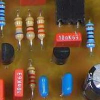
The assembled prototype
✈ Motivation • Background
The Power Split using just Resistors is a broadband Solution .... but with a poor Isolation.
This Design uses a Wheatstone Bridge (aka SWR Bridge) with a 1:1 Transformer. We used the WBC1-1TL_ and the WBC1-1L_ from Coilcraft, as
they were in our Designer Kit. The Datasheet suggests a frequency range of 0.25 ... 750 MHz (600 MHz). That's what we call Broadband !
The Performance Section will show, what can be achieved with a FR4 Board.
The Performance Section will show, what can be achieved with a FR4 Board.
✈ Function


The realised circuit also has some dc-blocking capacitors of 100 nF, to protect the transformer from dc, but for radio frequency, they can be regarded as a short.
The great advantage - with respect to the Resistor only version is the high decoupling between Port 1 and Port 2. This feature is bought in by the use of a broadband transformer. As we use resistors (3 x 50Ω) the overall Insertion loss remains at 6 dB. The isolation increases from 6 dB (Resistive Split, 2 Way) to (depending on frequency) something aound 40 dB. When using the specified frequency of the transformer (WB1-1L) at least 20 dB is possible.
✈ Performance


It can be seen, the the insertion loss is not always 6 dB. The isolation with the WBC1-1TL is better, this transformer has a slightly lower inductance of 9.5 µH versus 10.0 µH. The DC resistance is also lower, 75Ω versus 120Ω.
The imbalance from PORT2 and PORT1 mayst be explained with the asymetric setup.
✈ Downloads
✈ Credits
This Power Split Design was greatly inspired by the Website
of Claudio Girardi, IN3OTD. We would like to thank him for making his valuable Findings available online.
✈ Share your thoughts
The webmaster does not read these comments regularely. Urgent questions should be send via email.
Ads or links to completely uncorrelated things will be removed.
Your Browser says that you allow tracking. Mayst we suggest that you check that DNT thing ?
 ช้างเผือก


