Categories
Statistics
Since 08.08.2014
Counts only, if "DNT = disabled".
Your IP is 3.144.227.3
ec2-3-144-227-3.us-east-2.co
Counts only, if "DNT = disabled".
Your IP is 3.144.227.3
ec2-3-144-227-3.us-east-2.co
Info
เราจะทำแบบวิศวกรผู้ยิ่งใหญ่

25. December 2024
YOU RATED THIS ...
avg = 0.0 , n = 0


RF-T-PitayaBooster.php 6956 Bytes 25-11-2024 18:06:37
Red Pitaya Booster
RF TOOLBOX 3599 EDITION

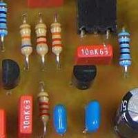
The assembled prototype
✈ Motivation
This is a Building Block for our Quantum Experimenters. As the Red Pitaya is based on an
FPGA, it enjoys high status among our Quantumopticians. Unfortunately, it has no High Voltage
High Speed Low Noise output.
✈ Functional Description
This is a cascaded approach using two instrumentation amplifiers. On the first sight, it
mayst deem strange to have a gain of Vu = 3.162277, but by that, we can maximise
the bandwidth of the overall system, because we use the maximum bandwidth for each stage.
(You can increase the bandwidth further by using more stages. See also
this website.)
The overall Gain using two stages is Vu = 3.162277 * 3.162277 = 9.99999.
The first stage may also add an offset voltage to get a true bipolar signal. This is selecteable with a jumper, for each channel.
The overall Gain using two stages is Vu = 3.162277 * 3.162277 = 9.99999.
The first stage may also add an offset voltage to get a true bipolar signal. This is selecteable with a jumper, for each channel.
✈ Accessories
✈ Downloads
✈ Performance
Performance data was measured with the INA118 equipped. We can not confirm the
claims in the datasheet : "A newer version of this device is now available".
It was not available for me - looks like chip-manufacturer are also attacked by viruses.

At 1 kHz, this circuit works like a charme

And can handle some overdrive (approx. 50%)

The Slew Rate Limiting kicks in. The used INA118 offers 0.9 V/µs (@ Gain=10).
The INA849 (different pinout) offers 35 V/µs in case you need it.

Small Signal Gain is - of course - much higher ...
✈ Share your thoughts
The webmaster does not read these comments regularely. Urgent questions should be send via email.
Ads or links to completely uncorrelated things will be removed.
Your Browser says that you allow tracking. Mayst we suggest that you check that DNT thing ?
 ช้างเผือก


