A small pulsed infrared Light Source for Photodiode Health Checks
✈ General Remarks
This is a small infrared source to quickly check the health status of photodiode amplifiers.
It is equipped with an af source generating pulses of approx. 999 Hz which are then used to
do some ask on a 32.768 kHz (1.00 MHz) carrier, delivered by an xco. And yes, we used
this calculator :-)
The device is battery powered by 2 x AAA, 3 V. (Battery Case: Keystone 2468)
And yes, you could also use an infrared remote control. Make sure you press a button which
sends a constant datastream, e.g. Volume up/down.
✈ The IR Diode
The diode used is a 15400585F3590 from Würth Electronics (Mouser, CHF 7.87 per 10). It has the following Properties :
Properties
min
typ
max
Unit
Peak Wavelength
λpeak
50 mA
850
nm
Centroid Wavelength
λcentroid
50 mA
845
nm
Radiant Intensity
Ie
50 mA
35
85
mW/sr
Forward Voltage
Vf
50 mA
1.5
2.2
V
Spectral Bandwidth
Δλ
50 mA
40
nm
Viewing Angle
2θ50%
50 mA
30
°
The Spectrum, as shown in the datasheet of Würth Electronics
✈ The Modulation : ASK
The upper trace in yellow shows the output of the LMC555 timer. The frequency determining components are
R1 = 5k6, R2 = 4k3 and C1 = 100 nF, which shall produce a 1.014 kHz squarewave. The middle trace (violet)
shows the output of the crystal oscillator. 32.768 kHz is assembled here. Those two signals are logically
AND-ed to result in the blue (bottom) trace, which is used to switch the IR diode on/off.
✈ Use • Troubleshooting • Experiments
The first experiment is done by using a Receiver made with the same IR LED, soldered to a BNC connector
and plugged into a high impedance input of an oscilloscope. Depending on the distance, we can see our
modulated as well as demodulated signal.
Distance TX - RX was 15 cm, U ≈ 500 mVppDistance TX - RX was 15 mm, U ≈ 1 Vpp
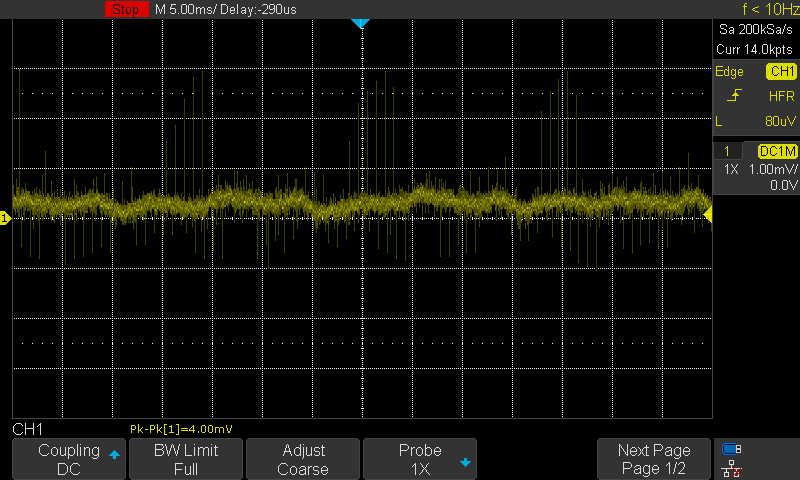
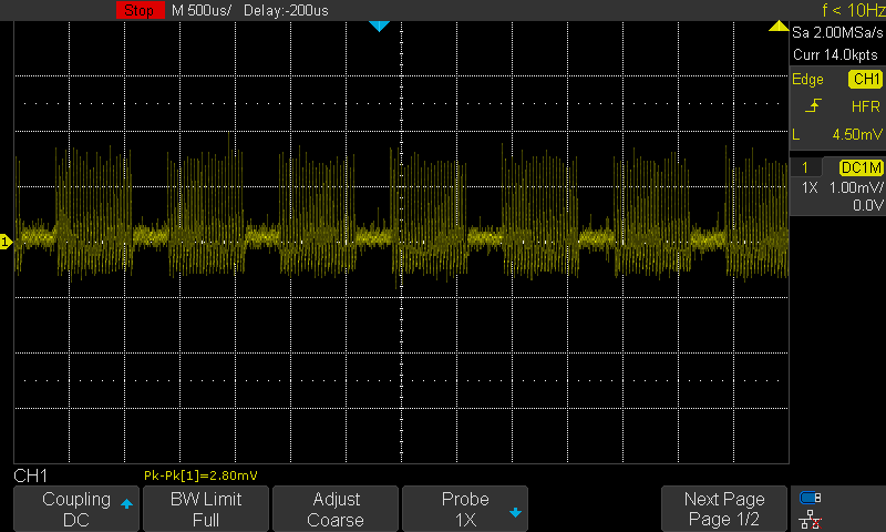
Now for the second experiment, we added a 50 Ω termination between the diode and the scope. We see,
that the signal decreases much in amplitude. We therefore compare the IR LED to a Si Photodiode (BPX-65),
which is optimised for 'RX' (from 350 nm to 1100 nm). Polarity not important.
IR LED (same), d = 15 mm and 50 ΩBPX-65, d = 15 mm and 50 Ω
We see, that the Si Photodiode produces a much cleaner signal, higher in amplitude.
We also see, that a BPX-65 can drive a high current into a 50 Ω load (when very close) to produce a
voltage of approx. 10 mVpp (which corresponds to ≈ 0.2 mApp). This will decrease with distance
and power used by the transmitter.
That's where the amplifier becomes part of the game. Comparing some Photodiode - Amplifiers, we see, that the gain
is usually high (10 ... 1000). That means that approaching a Photodiode - Amplifier with our Source must result
in some sort of Saturation - or a low amplitude when an amplifier stage is broken.
The QO-EL-0010 is a Photodiode Amplifier with a BPX-65 and 2 x GALI-39+. This would result in a gain
of approx. 40 dB (@ 0.1 - 1 GHz) ≈ Vu = 100. Distance is ≈ 10 cm. Minus the 40 dB introduced
by the TCBT-14+ at 30 kHz. Therefore, we would expect a signal of U ≈ 10 mVpp
QO-EL-0010 : brokenQO-EL-0011 : broken
QO-EL-0011 : functionalOSD15-5T : functional
We can see, that functional Photodiodes produce an output which is clean and high in amplitude.
✈ Downloads
✈ Share your thoughts
The webmaster does not read these comments regularely. Urgent questions should be send via email.
Ads or links to completely uncorrelated things will be removed.
Your Browser says that you allow tracking. Mayst we suggest that you check that DNT thing ?
 ช้างเผือก