 ช้างเผือก
Categories
Statistics
Since 08.08.2014
Counts only, if "DNT = disabled".
Your IP is 3.148.104.65
ec2-3-148-104-65.us-east-2.c
Counts only, if "DNT = disabled".
Your IP is 3.148.104.65
ec2-3-148-104-65.us-east-2.c
Info

เราจะทำแบบวิศวกรผู้ยิ่งใหญ่

22. February 2025
YOU RATED THIS ...
avg = 0.0 , n = 0

Magic-Tee.php 7372 Bytes 20-01-2025 15:28:39
Magic Tee Power Split • Magic-T Power Combiner
3 dB Insertion loss ... high Isolation
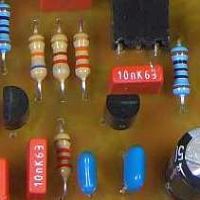
The assembled prototype
✈ Motivation • Background
The Power Split using just resistors is a broadband solution .... but with a poor isolation.
The design known as transformer power split • wheatstone bridge has good
isolation but high insertion loss. Now this design has a good isolation and a low insertion loss.
It is therefore known as the industry standard solution, as broadband performance is more important than cost.
✈ Function

The realised circuit also has some dc-blocking capacitors of 100 nF, to protect the transformer from dc, but for radio frequency, they can be regarded as a short.
The great advantage - with respect to the Resistor only version is the high decoupling between Port 2 and Port 3. This feature is bought in by the use of two broadband transformers.
The first transformer is a broadband 50 Ω to 25 Ω converter. The second one is a 1:1 transformer which has two windings in parallel, whereas twice 50 Ω (output impedance, Port 2 and Port 3) is transformed to 25 Ω.
The capacitance (TBD) is usually added to flatten the broadband behaviour. It heavily depends on stray capacitance. We left it out, as it worked just fine.
✈ Performance


It can be seen, the the insertion loss is slightly above 3 dB, at 100 MHz we measured 4.27 dB. Due to the symmetric setup, both outputs (PORT 2 and PORT 3) have similiar insertion loss.
The isolation decreases with frequency, but for this measurement, only parasitic capacitances were at work. The two pads foreseen on the pcb were unpopulated.
With the scope, we compared the outputs at 50 MHz. Input was -10 dBm (200 mVpp). We measured twice 120 mVpp, equivalent to -14.4 dBm or 4.4 dB Insertion Loss at 50 MHz.
✈ Downloads


✈ Share your thoughts
The webmaster does not read these comments regularely. Urgent questions should be send via email.
Ads or links to completely uncorrelated things will be removed.
Your Browser says that you allow tracking. Mayst we suggest that you check that DNT thing ?
|
t1 = 6799 d
t2 = 150 ms |
★ ★ ★ Copyright © 2006 - 2025 by changpuak.ch ★ ★ ★
|

|