 ช้างเผือก
Categories
Statistics
Since 08.08.2014
Counts only, if "DNT = disabled".
Your IP is 18.117.92.75
ec2-18-117-92-75.us-east-2.c
Counts only, if "DNT = disabled".
Your IP is 18.117.92.75
ec2-18-117-92-75.us-east-2.c
Info

เราจะทำแบบวิศวกรผู้ยิ่งใหญ่

28. March 2025
YOU RATED THIS ...
avg = 0.0 , n = 0

High_Voltage_Power_Supply_MC34063.php 18861 Bytes 04-03-2025 19:13:14
High Voltage Power Supply with the MC34063
A basic building block for a Geiger Counter (Nixie Tube)
Motivation
A lot of calculators out there suggest values, but for higher voltages, these circuits fail.
When generating high voltages (step-up, boost converter) the calculated duty cycle is typically (much) larger than 85.7 %. With a "standard
configuration", the necessary duty-cycle may never be reached. An extension, as described in
Application Note 920 by Onsemi is necessary.
This is often forgotten to mention and/or the presented circuit gives no clue either.
This website shall deal with especially this aspect of forcing higher duty-cycles by increasing the dischargeing current of the timing capacitor -
and therefore reach higher voltages :-)
The Application Note calls this "Ratio Extender Circuit". - Wow !
 The circuit consists of a diode and a transistor. Both are originally germanium types, but a schottky diode and a silicium pnp transistor also do the job.
(We tested 1N34A, AA113 and 1N5711 and all worked fine.) The function of the transistor is to increase the current when dischargeing the capacitor.
With the shown con- figuration, the off-time could be lowered to a minimum of 750 ns. This corresponds to a duty cycle of ~ 99.5 %.
The circuit consists of a diode and a transistor. Both are originally germanium types, but a schottky diode and a silicium pnp transistor also do the job.
(We tested 1N34A, AA113 and 1N5711 and all worked fine.) The function of the transistor is to increase the current when dischargeing the capacitor.
With the shown con- figuration, the off-time could be lowered to a minimum of 750 ns. This corresponds to a duty cycle of ~ 99.5 %.


The left picture shows the output waveform at Pin 2 (Switch Emitter) with the "standard configuration", whilst the picture on the right side is taken with the
'Ratio Extender Circuit'. For both measurements, the Pin 5 (Comparator Inverting Input) was tied to GND. The load at Pin 2 was 100 Ω and the supply was 6 V.
The timing capacitor was a 10 nF MKS2.
When generating high voltages (step-up, boost converter) the calculated duty cycle is typically (much) larger than 85.7 %. With a "standard configuration", the necessary duty-cycle may never be reached. An extension, as described in Application Note 920 by Onsemi is necessary.
This is often forgotten to mention and/or the presented circuit gives no clue either.
This website shall deal with especially this aspect of forcing higher duty-cycles by increasing the dischargeing current of the timing capacitor - and therefore reach higher voltages :-)
The Application Note calls this "Ratio Extender Circuit". - Wow !
The circuit consists of a diode and a transistor. Both are originally germanium types, but a schottky diode and a silicium pnp transistor also do the job.
(We tested 1N34A, AA113 and 1N5711 and all worked fine.) The function of the transistor is to increase the current when dischargeing the capacitor.
With the shown con- figuration, the off-time could be lowered to a minimum of 750 ns. This corresponds to a duty cycle of ~ 99.5 %.
The left picture shows the output waveform at Pin 2 (Switch Emitter) with the "standard configuration", whilst the picture on the right side is taken with the 'Ratio Extender Circuit'. For both measurements, the Pin 5 (Comparator Inverting Input) was tied to GND. The load at Pin 2 was 100 Ω and the supply was 6 V. The timing capacitor was a 10 nF MKS2.
Calculation
Circuit
The used circuit here is a standard application, expanded by the ratio extender circuit as well as a high voltage switching
transistor to isolate the controller (MC34063) from dangerously high voltages. A
BUT12A or a BUJ302A, which is designed for "high-voltage,
high-speed switching" mayst be used. In order to switch fast(er) a resistor is put in parallel to the base-emitter (of the switching transistor), as it is
important to clear the base fast from all charge carriers. The pictures below show the base-emitter voltage for two different values
of resistors.


On the left picture, the base-emitter resistor is 12 Ω, whilst on the right a 100 Ω is used. You mayst also notice, that the (output) voltage
is much higher, as well as the input current is lower and the transistor gets not that hot.
On the left picture, the base-emitter resistor is 12 Ω, whilst on the right a 100 Ω is used. You mayst also notice, that the (output) voltage is much higher, as well as the input current is lower and the transistor gets not that hot.


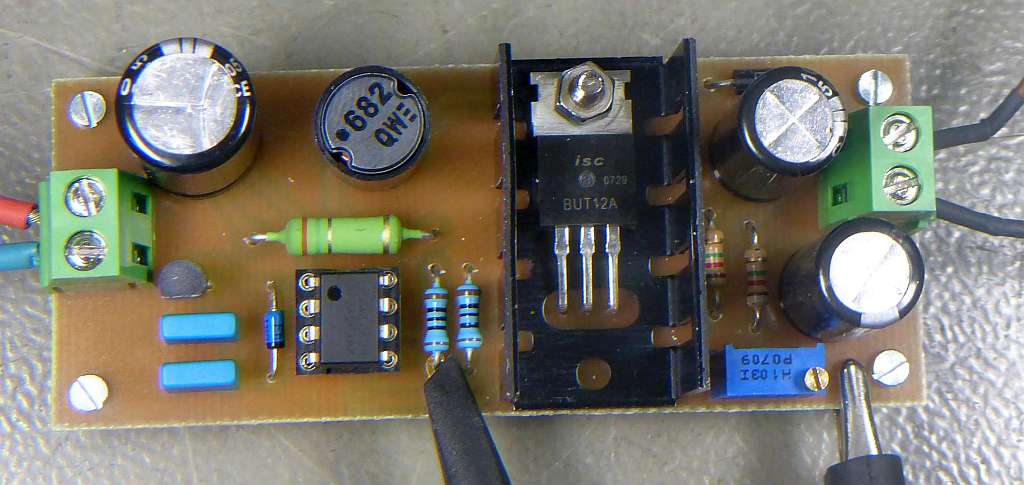
Board #1, 500 V • 2 mA
➤ Yes, the examples are tuned. Therefore, that the resulting inductor is one which is in my treasure chest :-)
This board uses 2 x 2.2 nF as timing capacitor, resulting in ~ 6.9 kHz switching frequency. As the input voltage was 12 V (±1%), the base voltage
divider was 100 Ω : 12 Ω. A BUT 12 A and a 6.8 mH inductor (ELC11D682F) have been used.
The output was loaded wit a 510 kΩ resistor, (approx. 1 mA of load current). The voltage could be adjusted from 400 to 540 volts. Input Power was 12 V * 0.17 A
= 2.04 W, Output was 0.594 W, resulting in an efficiency of ~ 30 %. The Ouput Ripple was about 40 mVpp (if you ignore the spikes, which may easily be filtered away
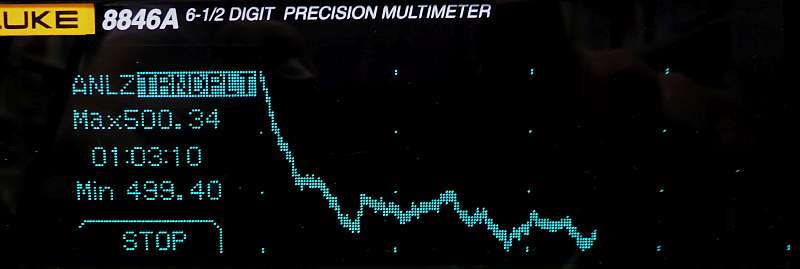
by an additional lowpass). The picture below shows the long term drift.
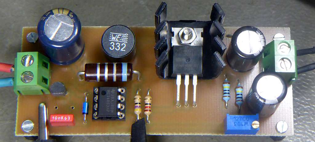
Board #2, 300 V • 3 mA
This board uses 1 x 10 nF as timing capacitor, resulting in ~ 4.9 kHz switching frequency. As the input voltage was 5 V (±1%), the base voltage
divider was lowered to 47 Ω : 12 Ω. A BUJ302A and a 3.3 mH inductor (3.3 mH 0.3 A ±20%, 7447471332, Würth) have been used.
The output was loaded wit a 200 kΩ resistor, (approx. 1.5 mA of load current).
The device was unable to start/reach 300 V. We had to increase the input voltage to 5.7 V to achieve normal operation.
Obviously the multiplication factor was chosen too optimistically.
Input Power was 5.7 V * 0.2 A = 1.14 W, Output was 0.45 W, therefore efficiency was ~ 40 %. The Ouput Ripple was about 80 mVpp.
The device was unable to start/reach 300 V. We had to increase the input voltage to 5.7 V to achieve normal operation. Obviously the multiplication factor was chosen too optimistically.
Input Power was 5.7 V * 0.2 A = 1.14 W, Output was 0.45 W, therefore efficiency was ~ 40 %. The Ouput Ripple was about 80 mVpp.
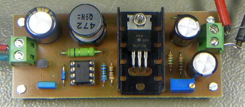
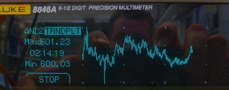
Board #3, 600 V • 1 mA
This board uses 1 x 2.2 nF as timing capacitor. A BUT12A and a 4.7 mH inductor (ELC12D472E) have been used.
The output was loaded wit a 620 kΩ resistor, (approx. 1.0 mA of load current). The current limiting resistor was 1 Ω. Adjustement was possible
from 390 to 630 V.
Input Power was 12.0 V * 0.2 A = 2.4 W. Drift within 2 h is shown in the picture below.
Input Power was 12.0 V * 0.2 A = 2.4 W. Drift within 2 h is shown in the picture below.
TROUBLESHOOTING
Do not choose the frequency too high. Some transistors may get in trouble.
5 - 9 kHz should be a good starting point.
If you do not reach the desired voltage, check the current / current limiting resistor.
A smaller value may be necessary.
Make sure your 1 Ω current limit resistor has not 100 Ω :-(
✈ Share your thoughts
The webmaster does not read these comments regularely. Urgent questions should be send via email.
Ads or links to completely uncorrelated things will be removed.
Your Browser says that you allow tracking. Mayst we suggest that you check that DNT thing ?
|
t1 = 6833 d
t2 = 238 ms |
★ ★ ★ Copyright © 2006 - 2025 by changpuak.ch ★ ★ ★
|

|