Categories
Statistics
Info
เราจะทำแบบวิศวกรผู้ยิ่งใหญ่

22. February 2025
YOU RATED THIS ...
avg = 0.0 , n = 0


Coaxial_Tank_VHF_Filter_Designer.php 8373 Bytes 14-06-2024 21:46:21
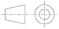
Coaxial Tank V.H.F. (Bandpass) Filter Designer
Sometimes also referred to as : Cavity Resonator, Cavity Filter, Topfkreisfilter

This Calculator is fully experimental. It is inspired by an article in QST, October 1964.
With the "Law of Scaling", dimensions are calculated to the frequency of interest. As the title suggests, this
is useful in the VHF range. Consider it as a starting point for optimisation :-)
On public demand, some words shall be added here. In order to gain some insight, it is the best way to design and build such a thing. Our center frequency is f = 1090 MHz, whilst the rod diameter shall be 10 mm. The assembly was not that challenging, as we used standard pipes made of brass. The bottom and top plates were made of copper. On the top plate a M6 screw with soldered nut is for the adjustement. We used sma connectors. (farnell #146-3066)

Fig: 1 :: View inside the bandpass-filter

Fig: 2 :: Fully assembled

Fig: 3 :: Insertion loss / amplitude response
Even the height was slightly higher (60 mm) than calculated, the disc-diameter of 20 mm was too big. The disc could be removed completely. The capacity made out of the M6 screw and the 10 mm (diameter) rod was sufficient to tune to the desired frequency. We measured an insertion loss of 0.8 dB with the network analyser and 0.9 dB with the spectrum analyser. The bandwidth was about 18 MHz (1080.95 to 1099.2 MHz), measured at -3 dB. (about 1.65 %). In order to make sure, that the tuning screw would not touch the rod, an 8 mm dowel was pressed into the rod. This may have been not that smart, as the overall Q presumably dropped by this.
Similiar projects with some building information :
A SIMPLE BANDPASS FILTER FOR 439 MHZ • Coaxial Resonators
On public demand, some words shall be added here. In order to gain some insight, it is the best way to design and build such a thing. Our center frequency is f = 1090 MHz, whilst the rod diameter shall be 10 mm. The assembly was not that challenging, as we used standard pipes made of brass. The bottom and top plates were made of copper. On the top plate a M6 screw with soldered nut is for the adjustement. We used sma connectors. (farnell #146-3066)

Fig: 1 :: View inside the bandpass-filter

Fig: 2 :: Fully assembled

Fig: 3 :: Insertion loss / amplitude response
Even the height was slightly higher (60 mm) than calculated, the disc-diameter of 20 mm was too big. The disc could be removed completely. The capacity made out of the M6 screw and the 10 mm (diameter) rod was sufficient to tune to the desired frequency. We measured an insertion loss of 0.8 dB with the network analyser and 0.9 dB with the spectrum analyser. The bandwidth was about 18 MHz (1080.95 to 1099.2 MHz), measured at -3 dB. (about 1.65 %). In order to make sure, that the tuning screw would not touch the rod, an 8 mm dowel was pressed into the rod. This may have been not that smart, as the overall Q presumably dropped by this.
Similiar projects with some building information :
A SIMPLE BANDPASS FILTER FOR 439 MHZ • Coaxial Resonators
✈ Note from the webmaster
VHF means Very High Frequency. To have a numerical value : 300 MHz (minimum). For a lower frequency, mayst we suggest
you try an approach with a helix bandpass filter ?
✈ Share your thoughts
The webmaster does not read these comments regularely. Urgent questions should be send via email.
Ads or links to completely uncorrelated things will be removed.
Your Browser says that you allow tracking. Mayst we suggest that you check that DNT thing ?
 ช้างเผือก
