Categories
Statistics
Since 08.08.2014
Counts only, if "DNT = disabled".
Your IP is 3.15.142.42
ec2-3-15-142-42.us-east-2.co
Counts only, if "DNT = disabled".
Your IP is 3.15.142.42
ec2-3-15-142-42.us-east-2.co
Info
เราจะทำแบบวิศวกรผู้ยิ่งใหญ่

25. December 2024
YOU RATED THIS ...
avg = 0.0 , n = 0


Arduino-Wanmod.php 9648 Bytes 26-12-2022 16:21:12
Arduino/Genuino Project "Wanmod"
A Frequency Selective Levelmeter, 99 kHz ... 29.999 MHz

View from the Front
| Frequency Range | 0.099 ... 29.999 MHz |
| Level Range | -99.9 ... -9.9 dBm, 7 dBµV ... 97 dBµV |
| Power Supply | 12 ... 15 V, 499 mA |
| Remote Control | yes |
| Measurement Bandwidth | see below. Approx. 5 kHz |
✈ The building Blocks • Functional Description

The mastermind of this design is of course the Arduino Nano Every. It displays the status on the 128 x 64 px oled display. The Arduino Nano also handles the Serial Communication (Can be USB or Envico).
The Design uses the "classical" double-super concept. A very high first IF is based on a SAW Dect Filter, running at 110.592 MHz with a Bandwidth of 1.728 MHz. (Epcos, B8104). A Mixer (NE/SA 612) powered by a 100 MHz XCO takes over and feeds a 10.7 MHz crystal filter, made out of 4 crystals. Hand-selected, of course.
The RSSI is is measured by an AD8307 in collaboration with an AD603. This circuit follows the recommendations in the datasheet. Instead of using the 10 mV/dB tap, replica builder should connect the output (Pin 4 of the AD8307) directly to the ADC. This will improve the resolution by approx. 1 Bit.

View inside. Classical superheterodyne approach.
PLEASE NOTE : You must use the programmeable version of the Si564. Partnumber we used is
564AAAA00012ABG - others may work as well. And second, SiLabs sold those oscillators to
Skyworks.
✈ The Crystal Filter, 2 nd IF, 10.7 MHz


The crystal filter is split into two blocks of four crystals. It is our standard design, found elsewhere on this website. The two blocks are separated (isolated) by a buffer amplifier (BUF 602, High-Speed, Closed-Loop Buffer from TI).
The 10.7 MHz Intermediate Frequency is also made available at the rearpanel (BNC) for demodulation e.a.
We used SQCB low ESR Capacitors from AVX RF (Sample Kit). Using 'any' capacitor may ruin your day (and the filter frequency response).
Using the Ningmod with this script, we swept at a Center of F = 9 MHz, Span = 40 kHz, with a Power of P = -20 dBm and N = 100 Points to measure the IF Filter Response. It looked liked this :

✈ Downloads
✈ Remote Control of the Wanmod
COM SETTINGS :
Set up the COM port inside the PC according to the following list.
• Baud rate: 115200
• Parity bit: None
• Data bit: 8
• Stop bit: 1
• Data flow control: None
Set up the COM port inside the PC according to the following list.
• Baud rate: 115200
• Parity bit: None
• Data bit: 8
• Stop bit: 1
• Data flow control: None
COMMAND SYNTAX :
*IDN?
Description: Returns the Device's identification.
Example *IDN?
Returns WANMOD 9.9 BY CHANGPUAK.CH
SETF:xx.xxx or SETF:x.x
Description: Sets the Output Frequency
Example SETF:19.1
Returns New frequency : 19.100 MHz
POW?
Description: Returns the measured Power
Example POW?
Returns -89.000 dBm
*IDN?
Description: Returns the Device's identification.
Example *IDN?
Returns WANMOD 9.9 BY CHANGPUAK.CH
SETF:xx.xxx or SETF:x.x
Description: Sets the Output Frequency
Example SETF:19.1
Returns New frequency : 19.100 MHz
POW?
Description: Returns the measured Power
Example POW?
Returns -89.000 dBm

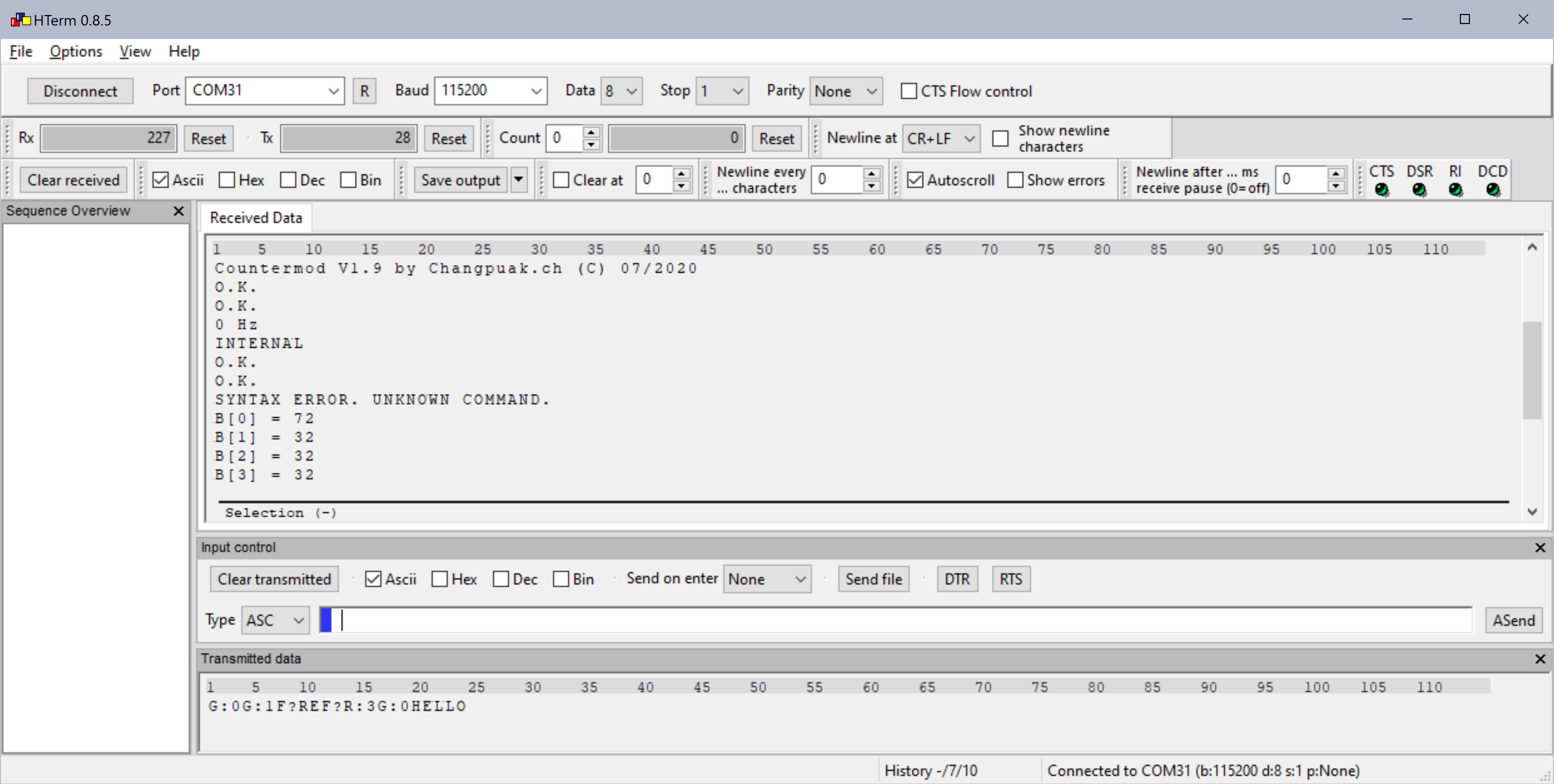
Remote Control with e.g. HTerm 0.8.5 from Tobias Hammer
✈ Optimizations

Antistatic Foam greatly reduces crosstalk from the Arduino ...
✈ Share your thoughts
The webmaster does not read these comments regularely. Urgent questions should be send via email.
Ads or links to completely uncorrelated things will be removed.
Your Browser says that you allow tracking. Mayst we suggest that you check that DNT thing ?
 ช้างเผือก


