Categories
Statistics
Since 08.08.2014
Counts only, if "DNT = disabled".
Your IP is 18.117.7.226
ec2-18-117-7-226.us-east-2.c
Counts only, if "DNT = disabled".
Your IP is 18.117.7.226
ec2-18-117-7-226.us-east-2.c
Info
เราจะทำแบบวิศวกรผู้ยิ่งใหญ่
22. February 2025
YOU RATED THIS ...
avg = 0.0 , n = 0


Arduino-SmartPowerSensor.php 8476 Bytes 09-06-2024 11:50:08
ARDUINO/Genuino Smart Power Sensor
50 Ω - 43 dBm to - 3 dBm, 1 MHz to 10 GHz
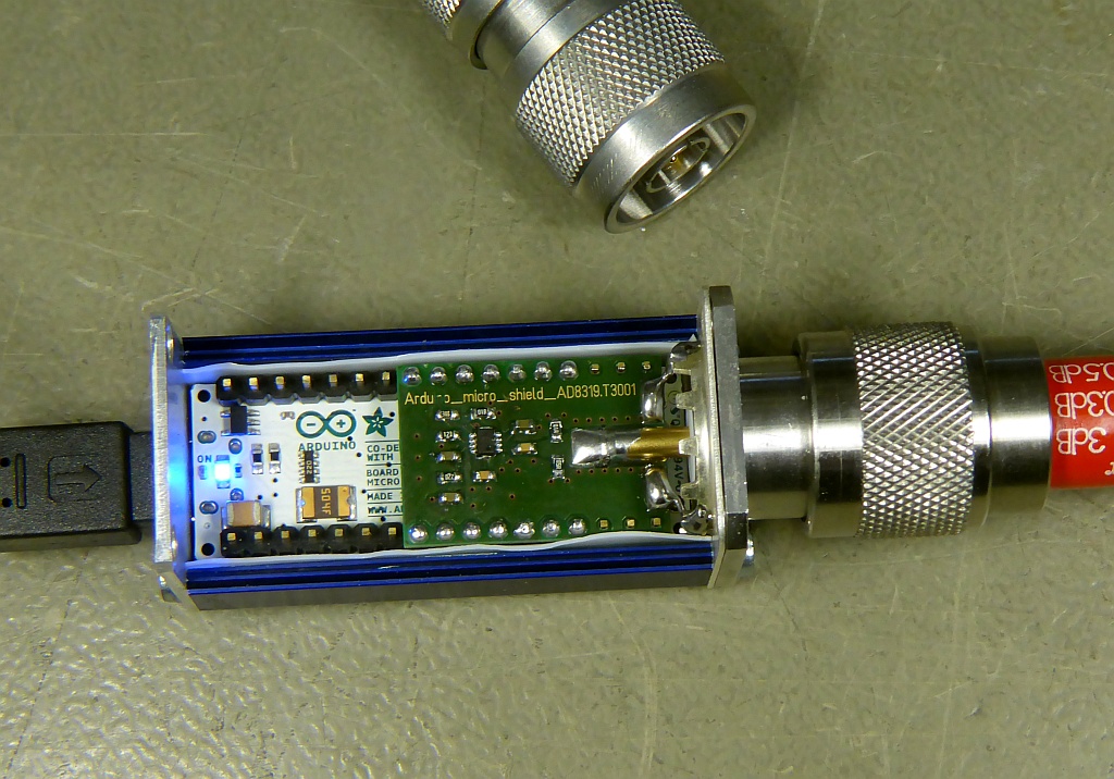
Not A Big Deal. Just squeezed an AD8319, a TMP101 and a 'micro' into a succobox.
• 45 dB dynamic range up to 8 GHz
• Fast measurement speed: 30 nsec typ.
• Manual frequency calibration & temperature compensation
• Multi-sensor capability (Up to 127 per usb host controller)
• Inspired by MiniCircuit's Smart Power Sensor, 'PWR-6RMS-RC'
• 45 dB dynamic range up to 8 GHz
• Fast measurement speed: 30 nsec typ.
• Manual frequency calibration & temperature compensation
• Multi-sensor capability (Up to 127 per usb host controller)
• Inspired by MiniCircuit's Smart Power Sensor, 'PWR-6RMS-RC'

✈ Hardware Description
The circuit mainly consists of an AD8319 from Analog Devices. Some decoupling capacitors as well as a voltage divider surround it.
The gain of the amplifier has been chosen to be v = 3, in order to map the expected maximum output voltage to a number close to 5 V.
As the temperature compensation looks challenging, we also packed a TMP101 on the bottom layer, close to the logarithmic detector.
On the arduino micro, the ISP header as well as the reset button have been removed to match the small geometry factor of the box.
✈ Arduino Sketch - The Code
Double click on code to select ...
/*
 Standalone Sketch to test Smart Power Sensor
 https://www.changpuak.ch/electronics/Arduino-SmartPowerSensor.php
 (Just to test the sensor and the I2C communication)
 Alexander C. Frank, 08.02.2016, Version 1.0
*/

#include <Wire.h>

byte I2C_address = 0x48;
int LogInPin = A5;
float LogInValue = 0.0;
float offset = 1023;
float gain = -1.0 ;

void setup()
{
Wire.begin();        // join i2c bus (address optional for master)
Serial.begin(9600);  // start serial for output
// INIT TMP101 - SET RESOLUTION TO 12 Bits
Wire.beginTransmission(I2C_address);
Wire.write(0x01);    // Configuration Register
Wire.write(0x60);    // R0 and R1 = 1
Wire.endTransmission();
}

void loop()
{

Wire.beginTransmission(I2C_address);
Wire.write(0x00);
Wire.endTransmission();

Wire.requestFrom(I2C_address,2);
int temp_hi = Wire.read();        // integer value
int temp_lo = Wire.read();        // fractional value
int temp = (( temp_hi << 8 ) | temp_lo ) >> 4 ;
float temperature = temp * 0.0625 ;

float amplitude = 0.0;

for (int i=0; i < 100; i++)
{
      LogInValue =  analogRead(LogInPin);
      amplitude = amplitude + LogInValue;
      delay(10);
}

amplitude = offset + gain * amplitude / 100.0 ;

Serial.print(amplitude,1); Serial.print("     ");

Serial.print(temperature,1);Serial.print(" ");
Serial.print((char)176);Serial.println("C");


delay(5000);
}
✈ Performance
The graph below has been measured with a Marconi 2022C. It was connected directly to the Smart Power Sensor with an N-male to N-male adaptor
and a 3dB attenuator (narda, 6GHz). The values shown are obtained with the sketch above. And yes, we know that evil manufacturers cut the graph
exactly there, where data is going to be disadvantageous. But we had no fancy synthesizer available at that time. (Onboard) temperature
was 31.4 °C.
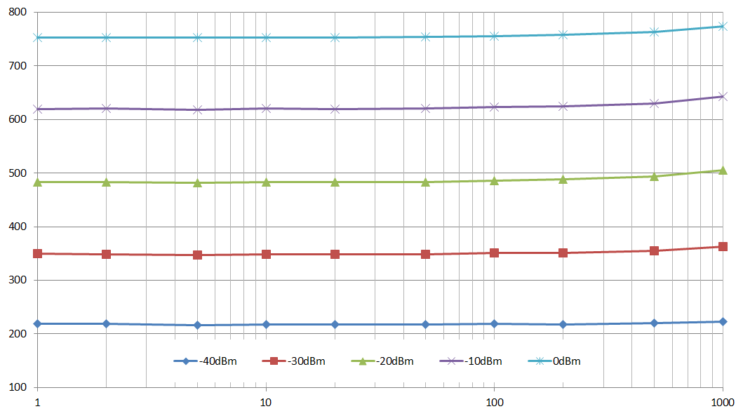
Raw Data (ADC value) vs. Frequency [MHz]
✈ Share your thoughts
The webmaster does not read these comments regularely. Urgent questions should be send via email.
Ads or links to completely uncorrelated things will be removed.
Your Browser says that you allow tracking. Mayst we suggest that you check that DNT thing ?
 ช้างเผือก


