 ช้างเผือก
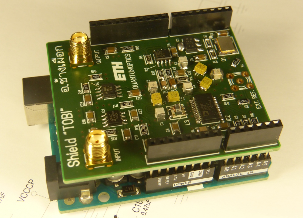
Categories
Statistics
Since 08.08.2014
Counts only, if "DNT = disabled".
Your IP is 18.191.167.138
ec2-18-191-167-138.us-east-2
Counts only, if "DNT = disabled".
Your IP is 18.191.167.138
ec2-18-191-167-138.us-east-2
Info

เราจะทำแบบวิศวกรผู้ยิ่งใหญ่

22. February 2025
YOU RATED THIS ...
avg = 0.0 , n = 0

Natalie and Nat King Cole "Unforgettable" 1992
Arduino-Shield-TOBI.php 13539 Bytes 07-06-2024 10:13:42
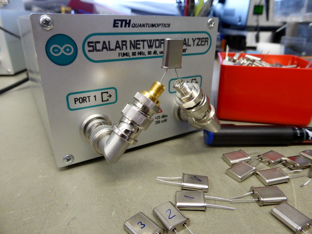
Arduino Scalar Network Analyzer, 60 MHz, 80 dB
Shield "TOBI"
This is just a 'proof of principle' (for physicists) or a 'FUMU' (for engineers). We wanted to verify, if this hack-together of building blocks
mayst work together.
The shield "TOBI", a hack together of this and
that and an Arduino Uno. Just to test
communication between an Arduino and a Python script. The largest effort was the Python script by R. Heslip. Thank you Sir, for sharing !
✈ Hardware / Software Description
The main task of the Arduino here is listening to the USB port. If some numerical data is received, this is understood as a frequency value.
It then programs the dds. Anything else is regarded as a request to read the adc and send the value to the Python script running on the pc.
The DDS is an AD9851 running at 150 MHz and the logarithmic detector is a AD8307. The hardware
was kept easy, as the calibration (intercept-point, voltage per dB) shall be done in the software.
The Python / Arduino script / code was developed by R. Heslip based on works of Onno Hoekstra. Only small adjustements were made.
➤ Get the Sourcecode from Github
➤ See a demonstration on YouTube by R. Heslip
➤ Visit 'Open Emitter', the Blog of R. Heslip
The Python / Arduino script / code was developed by R. Heslip based on works of Onno Hoekstra. Only small adjustements were made.
➤ Get the Sourcecode from Github
➤ See a demonstration on YouTube by R. Heslip
➤ Visit 'Open Emitter', the Blog of R. Heslip
✈ Arduino Sketch - The Code
Double click on code to select ...
// AD9851 DDS and AD8307 power meter
// sept 2013 RH
// small adjustments to match this project:
// https://www.changpuak.ch/electronics/Arduino-Shield-TOBI.php
// 02.11.2015 Alexander Frank

unsigned long DDS_CLOCK = 150000000 ;     // PLUS MINUS SOME PPM
unsigned long FREQ = 10625048 ;
unsigned long FTW ;
unsigned long REF_MUL = 0x0000 ;

// THIS IS FOR VERSION 2
int DATA = A4;
int CLOCK = A2;
int UPDATE = A3;
int AD8307 = A1;
char inputcmd[100];  // serial data input
int cmdindex=0;

void dBm_power()
{
  float dBm=0;
  int i;
  for (i=0;i<20;++i)  dBm+=(float)analogRead(AD8307); // average
  dBm=dBm/i;
  dBm = dBm - 869;
  dBm = ( dBm * 0.1014342 ) - 6.6 ;
  Serial.print(" "); // may help Python parser
  Serial.print(dBm);
  Serial.println(" "); // may help Python parser
}

void raw_power()
{
  Serial.print(" "); // may help Python parser
  Serial.print(analogRead(AD8307));
  Serial.println(" "); // may help Python parser
}

void SetFrequency(unsigned long frequenz)
{
FTW = (frequenz * pow(2, 24)) / ( DDS_CLOCK/256 ) ;

unsigned long pointer = 0b00000000000000000000000000000001 ;
for (int i=0; i<32; i++)
  {
    if ((FTW & pointer)>0) { digitalWrite(DATA, HIGH); }
      else { digitalWrite(DATA, LOW); }
    digitalWrite(CLOCK, HIGH);
    digitalWrite(CLOCK, LOW);
    pointer = pointer << 1 ;
  }

pointer = 0b00000000000000000000000000000001 ;

for (int i=0; i<8; i++)
  {
    if ((REF_MUL & pointer)>0) { digitalWrite(DATA, HIGH); }
      else { digitalWrite(DATA, LOW); }
    digitalWrite(CLOCK, HIGH);
    digitalWrite(CLOCK, LOW);
    pointer = pointer << 1 ;
  }
digitalWrite(UPDATE, HIGH);
digitalWrite(UPDATE, LOW);
}

void setup()
{
  Serial.begin(9600);

 // init dds
  pinMode (DATA,  OUTPUT);
  pinMode (CLOCK, OUTPUT);
  pinMode (UPDATE,  OUTPUT);

  SetFrequency(1000000); // 1 MHz default

}

void loop()   // Arduino superloop - where everything gets done
{
  char ch;

  long int temp;

// serial command interpreter
// enter a number to set the frequency, anything else shows power
  while (Serial.available()) {
    ch=(char)Serial.read();
    if (((ch >= '0') && (ch <= '9')) || ((ch >= 'A') &&
    		(ch <= 'Z'))) inputcmd[cmdindex++]=ch;
    if (ch == '\n') {    // parse command if its a newline
      inputcmd[cmdindex]=0; // terminate the string
      if ((temp=atol(inputcmd)) > 0) SetFrequency(temp);
      else dBm_power();
      //else raw_power();  // python has trouble with floats
      cmdindex=0; // reset command line
    }
  }
}
✈ Calibration
The AD8307 measures dBm, but the display of a scalar network analyser displays dB. You can therefore program the dds to output
a center frequency and read the adc. Connecting some (known) attenuators allows to create a graph of adc-value vs. attenuation
and so get the offset and pitch. We did that with excel, as it allows to display a trendline and displays the formula.
✈ Python
Python(x,y) is a free scientific and engineering development software for numerical computations, data analysis and data visualization
based on Python programming language, Qt graphical user interfaces and Spyder interactive scientific development environment.
We recommend you use pythonxy as it includes the GUI editor Spyder. DOWNLOAD IT HERE
Don't forget to change the Serial port to match your settings. (line 27)
Don't forget to change the Serial port to match your settings. (line 27)
✈ Downloads


✈ Pressing the "ACTION" button ... TESTING THAT THING :-)
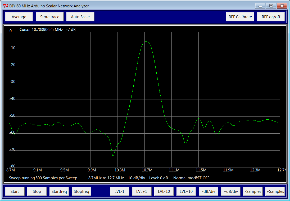
This very first test measures a ceramic filter for 10.7 MHz with l-c matching network. Even the calibration feature was not used,
the result is overwhelming. And the beauty of the graph makes you freak out ...
The second candidate was a Crystal Bandpass Filter from here

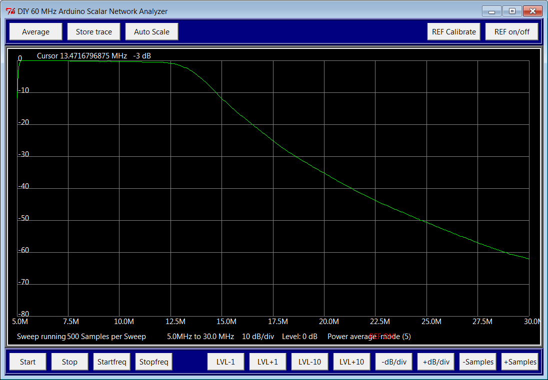
The third candidate was a lowpass of MiniCircuits (BLP-10.7)
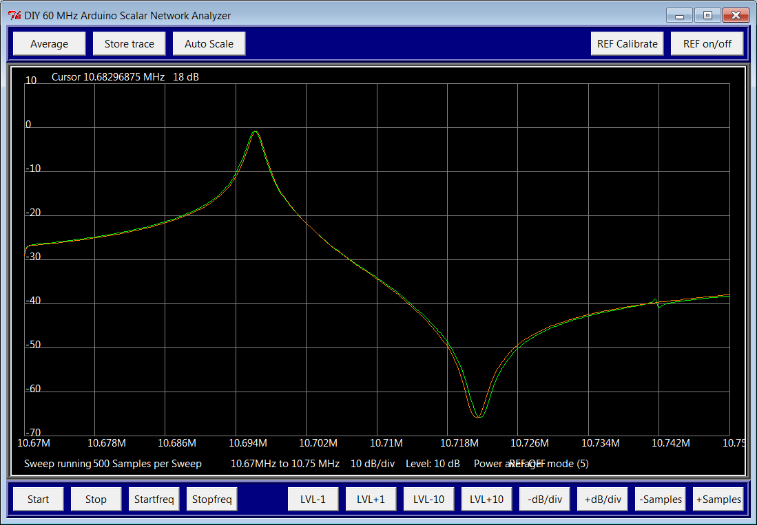
The fourth measurement shows the finding of crystal replacement data (by measuring the series and the parallel resonant frequency). Go here, if this is interesting for you. With the possibility to store a trace, it is easy to find matching crystals.
The second candidate was a Crystal Bandpass Filter from here
The third candidate was a lowpass of MiniCircuits (BLP-10.7)
The fourth measurement shows the finding of crystal replacement data (by measuring the series and the parallel resonant frequency). Go here, if this is interesting for you. With the possibility to store a trace, it is easy to find matching crystals.
✈ Hint
The lowpass, which was assembled here cuts off at about 50 MHz. This is due to the fact, that my treasure-box delivered only
inductors for that frequency. The maximum reacheable frequency is 0.4 * 150 MHz = 60 MHz. If you want to go to the absolute maximum,
use a crystal oscillator for 180 MHz and design a lowpass for 72 MHz. Anyway, a much bigger version is about to
come to life, so we did not optimize that.
✈ Share your thoughts
The webmaster does not read these comments regularely. Urgent questions should be send via email.
Ads or links to completely uncorrelated things will be removed.
Your Browser says that you allow tracking. Mayst we suggest that you check that DNT thing ?
|
t1 = 6799 d
t2 = 219 ms |
★ ★ ★ Copyright © 2006 - 2025 by changpuak.ch ★ ★ ★
|

|